Type C. OD and Plastic Timbre
- Jun 30, 2022
- 6 min read
Updated: Jul 13, 2023
Originally posted on the freestompboxes forum
Type C. OD
The OCD was my first veroboard build and a pedal I've always enjoyed as simple, no-frills distortion. Despite the wild claims of the original maker and the similarities with the Voodoo Lab Overdrive, I like how it sounds.
Despite that, there are some issues with it I decided to tackle, funnily enough mostly caused by the same few changes from the Voodoo circuit.
The main issue is an awful output impedance, of the order that it's not only bad on paper, but giving volume jumps even when switching pedals with decent input impedances after it, or cable capacitance causing a varying amount of treble loss.
At first, I had solved this by adding an output buffer, which I found out is similar to what the OCD v2 did, when traces became available (I had also added a capacitor before it to emulate the treble loss of a normal ~3m cable).
Another issue was the linear volume control, and then in general I thought it could have used a cleanup and standard E6 values for not critical parts. So here it is:

Op-amp. TL072, pretty much the standard for guitar inputs with the low current noise. I don't know why I should use the slightly noisier 082, but I have tried both.
Input stage. This is pretty much verbatim, I just made the input impedance a standard 1Meg, but also removed the input resistor because its noise gets amplified by everything, although small in value. It's a judgement call, noise and parts saving against current limiting and protection/reliability: I still haven't hit my face against issues caused by ESD on the input, so until then I choose the former. Gain stopper was removed to make this into an even cleaner boost if wanted: the original can already be very clean, why not go all the way and make the input stage go down to unity gain? Gain control law doesn't suffer, my spreadsheet tells me.
Clipping. Switched to plain 4148 diodes because the mosfets were used for their body diodes, and there's not any justifiable reason to use them (a previous research I did didn't show differences, at least in the VI curves), I had even made an audio comparison of the two and didn't hear much of a difference. They still go to Vref, not because there's much special about it, but because it saves me two caps and a resistor.
Tone. Moved between stages so it doesn't affect output impedance. "Hey why are the resistors the same, don't you have to subtract the series 10K?". As a friend pointed out, when the diodes are conducting, they're in parallel with the 10K, effectively dropping the total source impedance to very little, but when the diodes are conducting is when you need the tone control the most. This does mean in theory that the tone control cutoff and attenuation varies between the diodes conducting or not conducting at all, which I don't think it's that bad of a thing. Both simulations and side by side comparisons say that it's pretty much like the original. Log taper does give a better sweep but lin works well too.
Output stage. Just a low gain clean boost with common values and low impedances to bring the unity gain at about noon on the volume pot and buffer the output. The gain has been chosen by having in mind op-amp headroom and an output amplitude roughly equal to guitar levels with volume at noon, starting from the assumption of a worst-case ~1.2Vpp output from the clipping stage. Compared to the original "recovery" stage, the mid-frequency gain is 4.3 instead of 4.8, the treble cutoff is the same, the bass cutoff is 15 Hz instead of 40, an inaudible difference for guitar, and probably also for bass. It has been redone for low impedances and nicer E6 values.
Volume. 10K log pot for a lower output impedance than you'll ever need and no weird interactions. Log for a smoother control.
I'm happy with how it sounds, which is to say just like before. Maybe a little less latent fizz on the note tail? It was another thing that bothered me, so another win there. But also I made it my own a bit, and I'm proud of that.
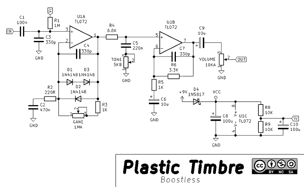
Plastic Timbre
A while back, I was shown the schematic of the Carl Martin Plexitone, again a straight-up distortion pedal. Some things about it didn't sit well with me, so I decided to rework it, with the focus of using few parts and standard values.

The input buffer on an high gain pedal always bothers me, it's just adding up noise to be amplified by the rest of the circuit, so I removed it and let the non-inverting op-amp do what it's good at.
Another intervention was to scale down the clipping stage to using 4148 instead of red LEDs, with the gain adjusted down by the ratio of their forward voltages to preserve the amount of clipping. There's a tiny difference in that the VI curves aren't proportional, but I'd say it's negligible. The clear advantage is for noise, since the amount of gain needed for the same amount of clipping is about 3 times less. The capacitors have been scaled too to keep the original frequency response.
I've rewired the gain preset switch so that at any moment negative feedback is preserved. Don't know if pops or worse are an issue with the original, but it didn't cost me anything.
The original tone control is interesting, I'd say: since the op-amp input is at virtual ground, the same response (save a little bit extra range on the treble side, due to the combination of values I chose) can be obtained with a passive shelving low-pass. This avoids the phase reversal and lets me combine the gain of this stage with the next into a non-inverting one.
Because of the scaling down of gain in the first stage and in this one, this circuit doesn't need the higher supply voltage or bipolar supply of the original, and it avoids clipping the op-amps even should you decide to run all knobs at full.
The recovery stage minimum gain has been chosen again to give a good output with the volume at noon. Its unusual placement is again to avoid clipping the op-amp meant to be your "solo" volume boost. In practice you'd probably set the volume somewhat lower than its maximum, so that gives an useful increase of available boost in the second stage before clipping.
The boostless version simplifies it even more, removing the boost and gain switches and leaving you with a same-sounding three-knob distortion:
Plasticizer
At this point, having already built the Type C. but liking both, I realized I could modify it into something similar to the Plastic with the simplest of switches, a SPST.
Reduced to these forms, the two circuits are both composed of a clipping stage with high gain and high bass cutoff, followed by a shelving treble control and a recovery stage. Sure, there are small differences, such as the different clipping topology, different values in the tone control, the additional low-pass in the recovery stage of the Type, but the most important difference is in the maximum gain and the higher bass cutoff in the clipping stage, so that's what the switch does, and it's a fun little addition.

Update
I've made a couple of very subtle tweaks to the circuit that I think are worth sharing, since they apply to all similar circuits.

First, the feedback LEDs: they might seem redundant, since the signal is already clipped, but in reality, with the diodes out of the op-amp feedback, this one is completely free to hit the rails; in this clipping arrangement, the output is determined by the diode forward voltage at a current which is the difference between op amp output and the forward voltage, divided by the resistance. As much as it's often called "hard clipping" (I prefer "shunt clipping"), at anything but the lowest gain and/or input voltage the peaks are further flattened by the op-amp. This makes the circuit dependent on op-amp saturation, whether because of supply voltage, saturation voltage or artifacts and noises of the specific chip. Thankfully, a pair of feedback LEDs completely eliminate this effect for all normal input amplitudes. While they're normally seen as a source of clipping, feedback diodes have the property of preventing op-amp saturation by quickly decreasing the gain to 1. I've chosen LEDs because the much higher forward voltage will mean no other difference on clipping behavior. This modification makes the clipping stage basically independent from op-amp choice even in this subtle detail. Since the bandwidth is already limited, a 072 is already undistinguishable from an ideal op-amp, and you'd have to use something with a very low unity gain bandwidth, like a 1458, and put it in "plastic" mode with the gain maxed to see some dB of difference. No more testing different op-amps, go outside or read a book instead.
The second change is in the series resistor before the diodes. I've made this smaller to reduce any eventual interaction with the low-pass filter. This has the side effect of slightly increasing the forward voltage reached by the diodes, but not much because of the reduced op-amp output swing with the LEDs. In a way it's a departure from the original, in another way it's closer because the low-pass doesn't depend on the diode conduction.
Vero Layouts


Comments