Trembling Satellite tremolo
- Jun 4, 2023
- 5 min read
The Tremulus Lune is by far the most popular DIY tremolo project, and for good reasons: it's a simple enough circuit that does all you expect from it, and more thanks to the large amount of controls. Unfortunately, the original circuit features an underwhelming input stage, and variations of it fail to address this issue properly.
I've talked about this before with the Pelota 2, which addresses the same issue in its own inspirations. In few words, resistors produce thermal "Johnson" noise, and even if a 220k resistor doesn't give the best input impedance, it still seriously compromises the noise performance. Quoting from there:
Even using 220kΩ resistors for an inverting input stage, already a big compromise in input impedance, the simple follower outperforms that by 6 or 7 times in terms of noise voltage density (the Johnson noise of the 220k resistors widely exceed the input noise of a TL072).
This is why I have modified the input stage of my Tremulus clone to a non-inverting buffer, which is simple enough to do. Mine was originally built according to the Aion version, which you'd think improves the situation by using lower value resistors and buffering the input; but the noise you save from the resistors is added back by the buffer and the result is the same.
Does this matter in practice? I think it does, because it means you can have audible "huffing" from the white noise cyclically being amplified then not, probably more annoying than just constant noise.
While I am at it, it's worth going over some "communication issues" with the Tremulus: the number of controls has sprouted multiple versions with multiple combinations of the full set of controls, with or without the separate "fine" and "coarse" rate controls, which are just an attempt in the original of getting good control from linear pots. Having built one with as many controls as possible (save for a single, rev-log "Rate" pot), I can say from experience that most people don't need these many controls on a tremolo, surely not on the "go-to" DIY tremolo.

Yes, it has two foot-switches and barely fits in a 1590B, more on that later.
It's worth giving credit to the Shoot the Moon for recognizing this issue first and picking the three controls I also consider the most useful: "Rate" and "Depth" obviously, and "Shape" being "Smooth", a continuous variation between triangle and trapezoid LFO. This could have been the end of the story if it offered an improved input stage and maybe an output pull-down resistor. Since it's not, there are a couple of other things worth going over again, such as handling different kinds of LDR and the volume going up at low "Depth" settings.
Schematic
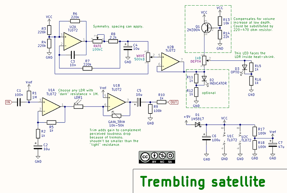
Here's the circuit. Having some experience with its inspiration and its qualities, I didn't change what was already working and focus on the aforementioned issues.
The input stage is non-inverting and with a small amount of gain. A buffer would already be an improvement, but any amount of gain one can put up front is going to improve SNR by the same amount, and 6dB are enough to make the difference between a noisy and a quiet op-amp. One could push this further, up to maybe 14dB, but from some recent tests with the Pevy, 8dB is a conservative limit that will practically ensure no audible clipping (with a 072 at 9 V). Of course, more gain in the first stage will mean less gain necessary in the second one, which can go down to zero if necessary.
The LDR and inverting amplifier configuration is kept as it is, which makes the signal path overall inverting. This is inaudible and has no practical consequence other than for parallel processing, and if your mixing device doesn't have the ability to flip the relative phase, that's the real problem.
I've tried a voltage divider configuration before this, but there were two problems with that:
The gain range is ultimately set by your choice of LDR (it will be less than that because the LFO doesn't turn the LED off completely); with the configuration in the schematic, you can aim for the ratio of dark to light resistance (D/L). With a voltage divider, as worked out for the VCA-1, the ratio is (R+D)/(R+L). So, unless you make the fixed resistor very small, which requires more input gain, you can't reach as much "Depth".
Even with a resistor close in value to the light resistance, there was a curious start-up issue where the voltage divider (going to Vref) would pull the reference voltage down and cause it to stay there. What do you do, add coupling capacitors? Nah, the arrangement in the schematic is much more elegant.
With the trimmer in the feedback of the op-amp, the gain can be adjusted down to zero. The actual setting would be a bit higher than the minimum resistance reached by the LDR in circuit, since this allows for a bit of gain to compensate for the fact that the gain will be lower than this most of the time. It's unlikely that a LDR can't go below 10k when placed right against a 5mm LED.
The main part of the LFO (U2A) isn't changed, except for the streamlined controls; it's your choice to include the extra ones as usual. Using a rev-log taper "Rate" pot gives very good control and makes it unnecessary to have two controls to do one thing. This LFO is used in the majority of modulation effects, and that's the case here as it is there.
I have to admit that using a smaller capacitor for C4 (for example 4.7u) and switching a second one in parallel with a foot-switch is a simple and fun modification, which allows to quickly switch between two different speeds (twice the speed in the example).
One small change is present at the LFO output: the original varies the LED source between the LFO and the positive rail, with the effect of the average voltage to the LED going up when "Depth" is turned down. Not only the perceived loudness increases anyway because the gain isn't cyclically decreased as much anymore, but it will increase even more this way because the LED will shine brighter on average, turning the gain up through the LDR!
My attempt at alleviating this issue is to have a lower voltage on pin 1 of "Depth", provided by an emitter follower. Since the BJT follower can only sink current into the op-amp, the emitter voltage has been set to be just above the positive peaks of the LFO, or those won't be attenuated and will cause a distortion of the LFO waveform. This probably isn't the only option (the attenuator in the Pelota 2 comes to mind), but it works.
A word about LED choice: I recommend a red one, not because the spectral response of the LDR matters (we can just trim the gain), but because its voltage drop matches well the LFO voltage swing with the values shown. Either way, it should be possible to use different voltage drops: my hint is to transform the LFO, R15 and R16 into their Thévenin equivalent, and then that could be matched to any LED.
Demo
Layout
Coming soon! Or will you be the one to make it?
Gotta say, I love your blog. Seeing this post brought back memories of an old thread I followed closely on TDPRI where a guy tried to recreate the short-lived and legendary fender harmonic tremolo using mosfets. The guy intended to use the circuit in an amp build, but I always wondered if this circuit would work in a pedal. Sure, there’s other implementations of the harmonic trem in pedals these days, but as as far as I know, they’re digital. https://www.tdpri.com/threads/exploring-fenders-harmonic-tremolo.791406/