Fuzz Face variations
- May 15, 2022
- 8 min read
Updated: Aug 22, 2022
The Fuzz Face is such a simple and popular circuit it's difficult to ignore it in the DIY world. Aware of the thousand tiny variations sporting different values, different part numbers or an added tone control, I wanted to share my own circuits based on it and some hopefully useful observations.
The Fuzz Face is made by two DC-coupled common emitter stages with global (series) feedback from the second emitter to (shunt) the first base. In topology it's very similar to some of the most common stages used in the days before op-amps when you needed a lot of open loop gain for example for feedback and linearity, such as in microphone preamps, but in a raw and unrestrained version. It's somewhat surprising how popular it is among beginners, since its very low parts count hides many quirks and pitfalls that aren't readily apparent.
A fun exercise is to approximate the voltages in a very quick and simple way, since better and more formal analysis has already been done: we know for sure that Q1's emitter is at 0V, and its base should then be a Vbe higher than that, about 0,65V for silicon in these circumstances (with respect to whatever is your "ground", assume NPN negative ground if you're more comfortable).
The next approximation we can make is that there's negligible voltage dropped across the 100k bias resistor: even for a low hfe Q1, this turns out to be at most 200mV, so it's not unreasonable. This means that Q2's emitter will be a bit higher than Q1's base, say 700mV. This in turn means that Q1's collector and Q2's base will be a Vbe above that, 1.35V, which just about what you get in practice. Now, if we keep going with the assumptions and ignore base current in Q2, we can say that for a 1k Fuzz pot we'll have 700µA of emitter and collector current, which means that if we want to drop 4.5V across Q2's collector resistor(s), its value needs to be about 6.5k. As full of assumption this crude approach of a few lines is, ignoring base current, actual Vbe, tolerances, it's about what you observe with silicon transistors.
Next observation: everybody knows the fuzz face is "low input impedance", but that's not the end of the story, everybody can guess that based on that grounded emitter at the input. Interestingly, when the Fuzz pot is maxed, input impedance doesn't stay low but rises with frequency. Since the signal at the emitter end of the 100k resistor is inverted with respect to the input, I feel like this is an example of Miller effect, but sorry if I can't elaborate further. The effect quickly goes away with the smallest rotation of the pot, but it's probably linked to why the effect sounds so different with maxed Fuzz.
Either way, you can think of the input impedance as the main factor limiting gain and shaping the frequency response, together with the source impedance. That's why this circuit in particular is so sensitive to source impedance, while many other "low impedance" circuits not so much (aside from the expected damping of the treble resonant peak).
The collector load on Q2 is split into two resistors in the original, for no other good reason that I found other than making the volume control (which is linear) more manageable by giving it a much smaller range to work with than the full 9V p-p. Other than that, it works just like any other attenuator, and the total AC load on Q2 doesn't change either way with 100k or more volume pots, so there's no effect on gain or clipping. That's why I decide to do away with it, just enjoy the bigger maximum output.
Final and most important point is oscillation. This circuit has a lot of gain and no other way to keep it in check than the Fuzz control. Of course that dramatically affects the sound, so we'd like not to rely on it.
When building a Fuzz Face as from the original schematic, chances are you'll be getting oscillation at maximum gain more often than not. This oscillation can go from a few to a few tens of kHz and not be audible by itself when not playing, but still have a great negative effect on the sound, especially on note tails. Here's a demo of a classical Fuzz Face I've breadboarded just to show the issue. I didn't have to try hard to get the effect, it was there every time:
Given how common this issue is, I bet it's part of the bad reputation silicon Fuzz Faces sometimes get, and another reason I find it surprising this is a circuit tackled by many beginners. Thankfully, the solution is there and is very simple: a small capacitor between base and collector of Q2, just big enough to stop the oscillation completely (I usually check with a scope, but as I've shown, it's easy to hear if it's there). Since the oscillation depends on stray capacitance and whatever is at the input, some testing might be required, unless you want to be conservative and go a bit larger. Usually between 100 and 470p works. You can see this in the schematics below.
Pinched Face
This is my latest and currently my favorite, albeit being very simple and somewhat unoriginal. I really like the result of having a small input capacitor in fuzz circuits, both because the result sounds more like a distortion pedal than a traditional buzzy fuzz and because of the interaction with the pickup causing a resonant peak. Other than that it's pretty simple and a good first one to show.


As you can see, the bass control is of the shelving type, isolating the traditional 1u capacitor and leaving in the end just a 4.7n. Other things to pay attention to are the beefy RC filter on the supply, which still drops negligible voltage given the current draw and allows the circuit to work well with almost any power supply, not just batteries; C5 is the important capacitor mentioned above, C3 might not be necessary but it's added insurance against spurious inputs; the output is taken straight from the collector, as explained above; a stopper resistor for the trimmer isn't necessary because the emitter resistance already limits current.
I've chosen the usual collector trimmer for biasing, even if rewiring the Fuzz pot to be in series with the capacitor and putting a trimmer in parallel would work too. This traditional arrangement works well, since at least in the case of maximum gain, whatever ends up being our transconductance, the resistance value resulting in our desired bias voltage (say 4.5V) is also the same value resulting in a given voltage gain, for a case of things canceling out.
You can see that the output capacitor and volume pot values are different. The tiny 10n capacitor and large 500k pot of the original don't actually affect the frequency response much at all (-3dB at 32Hz) but they come at a large cost in terms of output impedance, especially at low frequencies (read as volume jumps and change of timbre when switching effects or cable after it and increased hum). Since the circuit itself has pretty decent output impedance, I chose a combination of values that preserves most of that while not adding any significant load.
Here's a quick demo of the bass cut in action. Sounds just like a Fuzz Face when it's back to full:
Trimmed Face
This is another simple one. It started as a way to demonstrate that a PNP negative ground Fuzz Face is possible, but it also became a way to collect what I think are nice, quality-of-life additions to the circuit without affecting the sound.


Starting with the PNP version, we've already seen a negative ground PNP Fuzz Face inside the Fuzz Factory so it's an idea that works and has been mentioned around the web multiple times. The idea is that since the circuit is AC-coupled, you can flip it on its head and it will still work fine, unaware that the outside world uses the opposite ground polarity There are just a couple of things to be aware of: since the circuit itself uses the positive supply rail as "ground", it might be more sensitive to power supply noise. Also, oscillations might be more likely. Nonetheless, I've used the circuit above for months in a germanium fuzz face, without the input network or C4 and it worked fine.
I've tried to show the circuit in a way that makes wiring clear with the jacks. +9V and ground are the connections for the power supply, everything else just connects together.
The R1/C2 RC filter might seem unusual but this way becomes the most effective at fighting both oscillation and PSU noise.
C4 is the same capacitor mentioned in the other paragraphs. Here you can see R2 and C3 as last line of defense against oscillations. Other than that, I've mentioned that the implied voltage divider at the input is the main element controlling gain, so adding series resistance is a good way to limit that too, and you can find it in many commercial versions. It's also a good way to make your cheap and reliable silicon fuzz face sound smoother, more germanium-like if you want.
Finally, a characteristic of this version is BOM optimization: it uses the least values and they're all very common ones, despite being no discernible difference in the sound.
Fuzz Facelift
This one is an exploration of ways to improve the somewhat useless gain control in the original circuit. One simple and sacrilegious idea is to add emitter degeneration to the first stage, reducing gain and possibly contrasting the dulling of the sound with the increase in input impedance. The result is this:

As you can see, Q2 is fixed at maximum gain and instead gain is controlled on Q1's emitter. With Fuzz all the way up, you get a traditional Fuzz Face, with it all the way down, the input impedance reaches a simulated 250k at 1kHz, thanks also to the increased R2.
Q1's emitter not being grounded for DC can result in a difference in blocking distortion, as it's always the case when you add large capacitors to a clipping circuit. Blocking distortion is present in the original too though, so what I did was trying different values to get a similar behavior at different frequencies.
One happy side effect of emitter degeneration is that the bias becomes much more stable, to the point that trimming isn't necessary anymore across a large range of hfe, probably also for germanium. The values shown above should result in about 4.5V at Q2's collector. I find this a big upside for a beginner, even if there are a few more parts. It sounds like this:
Bazz Face
Little after I got interested in pedals, I wondered what would happen if one combined the two most popular simple DIY fuzz circuits: the Bazz Fuss and the Fuzz Face.
After some time, I've developed the idea into a circuit that is surprisingly simple and good sounding:
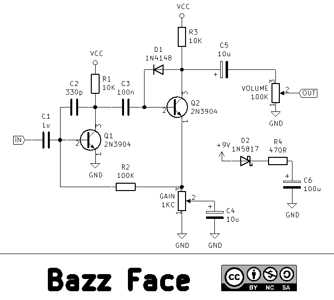
Again, a side effect is super stable biasing: the diode clamps the quiescent voltage of Q2's collector at one diode drop higher than the base, so no trimming is required.
Demo:
Build
The box that housed a SunFace first, a PNP trimmed face next and now a silicon Pinched Face is a tiny candy box, in which I somehow fitted three knobs, a 3PDT stomp with an homemade aluminium bracket to transfer the force to the bottom, the circuit, jacks and DC jack and also a battery! Once you get everything inside, it's actually decently sturdy and reliable. What was originally the questionable bias control is now the much more enjoyable bass control.

A final consideration: I've not specified any transistor model because, within limits, I think you can use whatever you like (read you have a lot of) and it won't change much. I've actually tried germanium transistors from an old radio and the popular, because used in the originals, BC108 and BC183. The results with these two were either disappointing or identical to using the humble 3904 or similar, and I liked it at least as much as the germanium transistors if not more.
This was an informative read. May I suggest a similar study on the germanium or hybrid Zonk circuit?