Caballero cab sim
- Apr 20, 2022
- 8 min read
Updated: Aug 22, 2022
I have a long secret relationship with cab sims. I'm talking about analog cab sims, the ones that aren't anything more than a very specific equalizer. I know that digital and IR cab sims exist and are very popular, and can account for other characteristics of a guitar loudspeaker, but those are both outside my interests and my capabilities. I think a glorified filter can be very effective indeed for playing without a speaker and a microphone, quietly or not, and surely its hardware, being simple and made of common parts, is surely more within the capabilities of any DIY enthusiast.
I've collected and simulated many circuits, some quite impressive, some very simple, some like the astrosim that manage a complex frequency response all within the feedback loop of a single op amp, but I think whether to keep the circuit simple or not, they missed the mark a bit. My favorite is probably the series of Marshall cab sims found in the JTM and JMP1 amplifiers and then copied by Blackstar in the newer HT amps.
While the following circuit is completely original, I've taken inspiration from all those sources, keeping the features I liked more and implementing them in my circuit. There's no point denying the usefulness of the sources in making this.
So, where do I start to make something more to my taste? For a preliminary analysis, I've checked the frequency response charts published by both Celestion and Jensen on their site. While those surely have to be taken with a spoon of salt, because little is known of the test conditions, I think they still represent both a good starting point and a good goal to achieve.
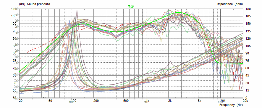
Since I didn't want to emulate one particular speaker, and good luck with that, I put many of them together to get an average picture that hopefully also removes some inconsistencies, both from the same maker and between them. This is a collection of some more or less randomly selected 12" Celestion speakers (g12h, g12t75, g12m green, blue, seventy80, g12 EVH, g12 cream):

I made this myself with photoediting. Instead the Jensen website offers a comparison tool itself, even if I'm not sure the result is better. You can still see the g12h in the background because it was used to scale to the same axes:

We can summarize the main common frequency response characteristics then:
Bass roll-off under 100Hz at 10 (Celestion) to 18 (Jensen) dB/octave.
for Celestion: slight slope from 0dB (reference) at 100Hz to +5dB at 1kHz
for Jensen: a wide notch at about 400Hz, 5-10 dB less than 100 and 1k.
for Celestion: a narrow notch of -5dB at 1.5kHz
Both: a wide peak centered at 2.7-2.8kHz, about +12dB with respect to 100Hz, with Q of around 1.1
Very steep treble rolloff starting at about 5kHz. Seems to be about 46dB/octave on the Celestions and 16-28 on the Jensens.
High shelf above 10kHz at -15/-20dB
And here's my solution:

Given the summary, it should be easy to follow because it's a logical and ordered implementation of it. The order of the stages isn't too critical, but I tried optimize headroom and noise both. A note I want to make is that the circuit is pretty flexible in the amount of controls you can have. you can exclude any of them and even make a version without controls! That's why for each I suggested a "stock" setting, but of course you can use any you prefer.
U1A is the input stage. Gives good input impedance and amplifies the signal a bit to give the right middle frequency response for points 2 and 3.
The mids control is a bridged T notch. Of course those are nothing new, but I liked this variable version found in the DSM cab sims because, unlike others, it can go from completely flat to standard notch while keeping the same center frequency. I iteratively changed the values to obtain a filter that had the right, close to 400hz center frequency while being narrow enough to only affect frequencies between the other filters (so between 100 and 1k). I found out that since notch depth increases together with bandwidth, using a stopper resistor with an otherwise deeper notch resulted in an overall wider bandwidth than a filter optimized for that notch depth. This takes care of point 3.
U1B is just a buffer to isolate the Sallen-Key high pass filter that gives me the 12dB/oct cut under 100Hz as for point 1. This and the following low pass filters are something I liked from the Marshall circuits. I've tweaked the values for my desired cutoff of 96 Hz and a Q of 0.82. This with R13 shorted. When the switch is open, the filter becomes rather sloppy with a cutoff at 53 hz and Q of 0.45, but this is exactly what I needed to instead approximate the bass rolloff of the Celestion speakers. Other than that, I usually find cab sims to be a bit too bassy, also because the rolloff isn't as steep or even absent, and this gives me two good low frequency settings that are different enough.
The next two stages are two identical third-order Sallen Key low pass filters. These take care of point 6. The Marshall ones combined a second order with a third order, but I thought I could do a total sixth order rolloff since it sits nicely between the eighth-order-like Celestion and the fourth-order Jensen. The cutoff and Q have been again chosen iteratively to obtain the desidered final response. Individually, the filters have a cutoff around 5kHz and Q of about 1.14 but what matters is that they're stable and give the desired response. You can find on the schematic alternative sets of values which will give very similar results. I always try to use few and simple values, even if in this one you might find E12 resistors, because I felt the extra accuracy was necessary. I hope that between the four alternatives you can find one that uses values you have at hand.
U2B is a gyrator based RLC series resonant filter. This one is responsible for the narrow notch at 1.5kHz at point 4.
U2D is a difference amplifier that does two things at once. It sums the output of the previous filters with the "shelf" path, taken directly from the first stage. This trick from the Blackstar cab sims lets the very high frequencies shelf at -22dB or so instead of descending into nothing. This will keep a very small amount of high frequencies, instead of the empty wasteland that would be there otherwise. This network feeds in the inverting input, because the output of the three filters is overall inverted when accounting for phase shift. The cutoff and gain are chosen so that this has very little effect on the rest of the response. Point 7 is dealt with. The second thing happening here is the gyrator based band boost in the feedback. This is responsible for the wide peak of point 5. I think this is a major and noticeable feature of the frequency response, and one that is often overlooked in other circuits, maybe implemented with a resonant low pass filter that gives a smaller and narrower peak. Since it's so important, I dedicated two controls to it. The peak one varies the center frequency, giving a wide range of sounds without invading the other filter ranges. The high control instead lowers the gain of the peak to almost the same as the middle frequencies.
As last addition, I realized that I could move the U2B gyrator between two positions to get either the 1.5k notch of Celestions or the bass peak of Jensens. Previously I had just left them as different alternatives, but why accept compromises when you can have both? For reusing most of the parts the results are very good. Gyrator connected to the input stage is "J" and connected to C14 is "C". Anti-pop resistors are always good practice, but they shouldn't be necessary, since everything is sitting at Vref and there's practically no DC voltage potential that can develop across the caps. Again, modularity is the word: if you don't want this switch, just wire it one way or the other. The values are standard either way.
To show the results, I overlaid two preset responses on the previous graphs, so you can see how close or far they are from the target:


I think the resemblance with the Celestions I chose is pretty good. The bass is on the loose setting, and I've shown the full sweep of the mids control, so you can see that you can get everything in between.
The Jensen similarity is good too, considering it was just an extra exercise for me to match two brands of speakers instead of one. Here the bass setting is tight and the mids are scooped. Thanks to the C/J switch I don't have to give up the buffered mids control to have the gyrator giving me the extra 5dB at 100Hz.
Then here's some nice measurements I made with ARTA. All is good while you're in simulation, but when you really enjoy your circuit you better check, or fool yourself you're hearing exactly what you wanted.


In case you're wondering, the high frequency noise is from the messy breadboard being in between my monitor and PC.
Finally, let's talk about the headphone amplifier. One thing I liked about the astrosim is having one: it makes it a great portable practice tool for example, so I made my own. It's a pretty standard 5532 based headphone amplifier, using the second half as follower to boost the current output capability. It's more than adequate for this use, and misses being close to hi-fi mostly for being single supply and having a somewhat limited, by design, 15Hz-33kHz bandwidth. The maximum gain is 5.7 and I found it pretty loud, with a comfortable volume around half. Since you might be more confident with hearing damage or just have higher impedance headphones than mine, you can increase the gain by increasing R27, or decreasing R25 while increasing C22.
But how does it sound? Here's a quick demo of it. More details in the descriptions.
Hope you enjoyed this. I'm always eager to know if someone tries the circuit and what they think of it.
Update: build
I've finally finished building a permanent version of this circuit. It was one of my most exhausting builds so far, not because of its complexity but because of unexpected challenges. I've had to change solder type four times during this period, with the third one ending up making my board conductive. Figuring that out and why was the biggest waste of time, but at least I was able to save my boards from it, after even trying my luck with a new etch. It was also the first time I've burnt a LED, probably because I was thrown off by not having a bypass switch and the led being hidden under the board. Of course it happened to be embedded in the nice epoxy layer I had poured on top so I had to drill it out (they're also oval-shaped LEDs, which makes everything the more fun). I don't want to get into more particulars, but this was anyway a pretty compact double sided home etch board, with no space wasted in the 1590B and creative solutions for connecting the top traces. I even had to make a spacer frame against the lid from a plastic sheet to have enough depth. In the end, I have my new favorite cab sim in a pretty and small package. Here are some pictures and a new demo.


Hey !
Thx for sharing ! I would like to try the circuit but I'm not sure about what capacitor are mlcc, styroflene film and Mylar capacitor... Any hints on that ? Thanks for taking the time to writing down your expermientation... thoses are really valuable.
Cheers
Dimitri
notice me senpai