Blue Pilot, an integrated Blues Driver
- May 2, 2022
- 5 min read
Updated: Aug 22, 2022
Hello everyone. The Blues Driver always pops up among the most popular overdrive pedals, no doubt because many people like how it sounds, but also because it's easy to find and relatively affordable, being from one the biggest pedal company in the world. It's not as popular in the DIY world, aside from mods, probably because it's not the smallest circuit and uses many transistors in a discrete op-amp configuration. Also since you can get it anywhere for cheap, I guess most people just don't bother.
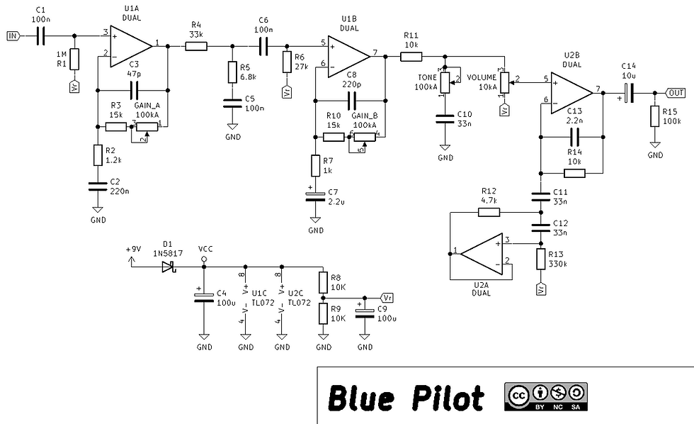
I think that's a pity, because it's an interesting circuit which I'll go through (you might want to grab a schematic of the original), while showing you my attempt at making a version using IC op-amps, which results in a simpler, cheaper and more DIY-friendly circuit. Also in this more familiar-looking form, you can use it an inspiration to make your own BD-flavored distortion.
The discrete op-amps
So, about the discrete op-amps. The Blues Driver features two such stages, with JFET input devices and a PNP BJT for the second amplifier. Their open loop gain depends heavily on the JFET used, but simulating/calculating with the typical transconductance found on the datasheet, it's probably not too far off to estimate it at above 300-400. That's not much compared to any integrated op-amp, but it's not too little either, especially for small closed loop gains when the gain knobs aren't maxed out. This should result in the linearization and abrupt clipping transition associated with op-amps and large loop gain, so it's not unreasonable to use an integrated one, especially since examples of op-amp clipping are already everywhere (this included? :) ) and well liked despite their bad name. I don't have an original to take measurements from, but simulation shows very similar transfer curves for both versions.
There's other things to consider of course. Clipping is symmetrical and headroom is 8V p-p, which means basically the full supply voltage as advertised on the schematic, because of the capacitance multiplier on the supply rail. I really liked this being here, but it's one thing we can happily get rid of, since op-amps benefit from very good PSRR.
Anyway, a TL072, as many other jellybean op-amps, has at most 6V p-p of output swing on a 9v supply, so this difference in headroom has to be compensated in gain to get the same amount of clipping and same input headroom. This is one reason the values for the feedback divider are different from the original for the first stage. This doesn't apply to the second stage since the voltage at its input will be a fraction of the original's exactly because of the reduced gain and output swing of the first stage, and the two amplifiers being the same, that's already the same 6/8 ratio to apply to the second stage.
I leave the choice of op amps to you not because it really matters much, as long as you use one with a "standard" output swing (~1V from each rail) and reasonable bias currents, but because some might not recover well from the large common mode signals with this amount of clipping. That said, I used a TL072 which is one of the worst in this regard and it seems fine.
A second reason the values have been changed is to compensate for finite open loop gain. While the open loop gain in the original is reasonably high, it's still lower than that of the 072, so this needs to be taken care of to get the same closed loop gain. Capacitor values have been tweaked to get a similar high and low frequency response as the original in simulation.
The tone stack
Next, let's talk about what's between the two op-amp stages in the original: what the keen-eyed will recognize as a fixed FMV tone stack, followed by clipping diodes. This looks very interesting and suggests a design based on a Fender pre-amplifier, with the tone stack placed between two gain stages, but in reality it turns out to not be that exciting.
First the tone stack: at first look you can already tell its controls are set to maximum for middle and bass and minimum for treble. What this results into is basically a shelving filter attenuating by 6 dB everything above 100Hz, with a tiny amount of ripple above that. I've analyzed this together with the RC high-pass at the input of the next stage, which cuts a not negligible amount of bass, and you'll see why doing this is legitimate shortly.
Knowing this, I set myself for making a simpler filter that achieves the same response. This is composed by everything between R4 and R6. The difference is at most -1dB at 10kHz. Good luck hearing that, especially before some clipping.

Now, the diodes. I was a bit surprised to find that these aren't doing much at all. In hindsight, it makes sense because they're after all the attenuation from the tone stack, which is also an equalization curve, so that even with the full 4V peak swing from the previous stage, only frequencies below 150Hz have enough amplitude to clip, and even then the conduction is very limited, a few μA and correspondingly low forward voltages of about 0.9V. That's why I've decided to remove these altogether. It's safe to say that the op-amps are the main source of clipping in the circuit, and the contribution from the diodes might or might not be audible. If someone has a blues driver to pull the diodes out from for an A/B comparison let me know.
The tone control
Here comes another block which looks more interesting than it is. The tone control is made from two filters, a fixed high shelf and a variable treble cut/relative boost. The result though, is very similar to that of a simple variable high shelf like those found in many pedals and guitars, save for a bit less ripple in the pass band. So I swapped it out for exactly that, tweaking values and loading from the volume pot to get a close response and good sweep across the tone control:

I invite you to focus on the extremes of the sweep and the very small ripple of the simpler version. The center position graph is an approximate match since the taper of the two tone pots is different and the sweep slightly too. The high-pass at 45Hz is negligible too, but if desired a 220nF capacitor before the volume pot takes care of that.
The gyrator stage
The gyrator stage adds 6 dB of boost at around 120Hz with a Q of about 2.4. I didn't have to change much here except tweaking some values to achieve the same response with an op-amp buffer, which will have resulted in a narrower and bigger peak if left as it is. I've also used some more friendly values overall, in this stage and in the rest of the circuit. You can see some E12 values, but they're only used when the increased accuracy in frequency response or gain is necessary, otherwise I had no reason to use more than the humble E6 series, since some careful scaling and tweaking could get me where I wanted.
The protection diodes at the inputs have been left out, because even in the worst case of a full swing at the peak frequency (which in case you're wondering will be LOUD) the differential input voltage is within limits and there's no noticeable difference at the output.
Demo
Here's how it sounds (warning, previous version with wrong gyrator values, but you get the idea):
Conclusion
The BD-2 is one of the most popular overdrive pedals around, but hasn't got as much attention in terms of DIY. With this version I hope to have given both an easy to build version and a starting point for people to start experimenting with this kind of circuit.
This is really cool- just saw Brian’s video and built it out in KiCad. Looking forward to checking it out.